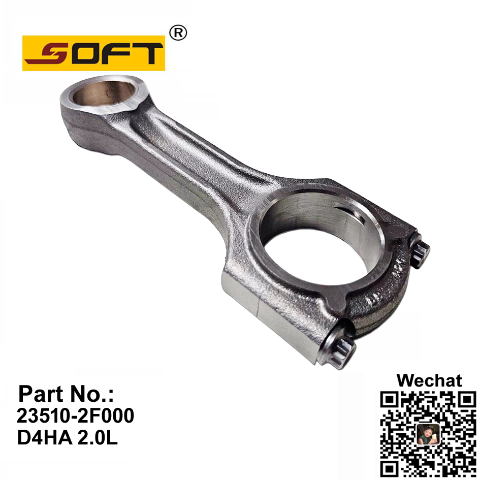
The exact moment linear combustion pressure converts into usable rotational torque represents the most demanding mechanical juncture inside an internal combustion engine. When ignition occurs, expanding gases force the piston downward, generating thousands of pounds of compressive load. The Connecting Rod takes the absolute brunt of this violent impact. Operating as a dynamic lever arm, it dictates how efficiently energy transfers to the crankshaft. An improperly specified or poorly machined rod leads directly to catastrophic engine failure, shattered cylinder blocks, and voided warranties. Understanding the strict physics of this force transfer forms the foundation for evaluating, sourcing, and specifying the correct materials, bearing types, and beam designs for high-performance builds and OEM remanufacturing.
Key Takeaways
The connecting rod acts as a dynamic lever arm, converting the reciprocating motion of the piston into the rotational motion of the crankshaft while absorbing massive inertia forces.
The rod-to-stroke ratio fundamentally alters engine kinematics, impacting piston speed, cylinder wall side-loading, and torque curves.
Material selection (cast, forged steel, aluminum, titanium) dictates a rod's ability to handle specific stress types, acting as either a rigid transfer mechanism or a shock absorber.
Application-specific engineering dictates selection; high-torque diesel applications require different structural profiles than high-RPM gasoline engines.
Mitigating implementation risks requires strict adherence to bearing clearance tolerances, fastener torque specifications, and proper lubrication management.
The Physics of Motion: Reciprocating to Rotational
Combustion Force and the Piston Downstroke
Force transfer begins the millisecond the air-fuel mixture ignites. The resulting explosion creates rapidly expanding gases that push against the piston crown. This event generates immense cylinder pressure, often exceeding 1,500 PSI in modern forced-induction applications. To understand the load, consider a piston with a 4-inch bore. That piston has roughly 12.5 square inches of surface area. At 1,500 PSI, the rod absorbs over 18,750 pounds of compressive force during a single power stroke. The piston drives downward, transferring this raw kinetic energy directly into the small end of the rod. The rod must withstand this sudden, violent compression without buckling or deflecting. If the cross-sectional area of the shank lacks sufficient rigidity, the metal yields, leading to immediate structural failure and engine destruction.
The Lever Arm Effect on the Crankshaft
Mechanical advantage dictates how effectively combustion pressure becomes torque. The rod functions as a rigid link connecting the piston pin to the crankshaft journal. As the crankshaft rotates, the geometric angle of the rod changes continuously. At top dead center (TDC), the rod stands perfectly vertical. In this position, it offers zero mechanical advantage for rotation. The downward force simply pushes straight into the main bearings. As the crank journal moves past TDC, the rod angle increases, creating a lever arm effect. Maximum mechanical advantage typically occurs when the crank pin reaches approximately 70 to 75 degrees after TDC. This shifting geometry means the torque delivered to the crankshaft is never constant. It rises and falls based on the precise angle of the rod relative to the crank throw.
The Impact of Rod-to-Stroke Ratio (Kinematics)
Engine kinematics rely heavily on the rod-to-stroke ratio. You calculate this by dividing the center-to-center length of the rod by the total stroke length of the crankshaft. This mathematical relationship fundamentally alters how the engine breathes and operates on the shop floor.
High Rod Ratios (e.g., 1.8:1): Longer rods reduce the maximum angle relative to the cylinder bore. This decreases side-loading friction against the cylinder walls, reducing wear on the piston skirts. It also increases piston dwell time at TDC, allowing for a more complete combustion burn before the exhaust valve opens. Engine builders favor high ratios for high-RPM naturally aspirated track cars.
Low Rod Ratios (e.g., 1.5:1): Shorter rods create a steeper angle during the stroke. This increases side-loading and accelerates the piston away from TDC much faster. This rapid acceleration creates a stronger intake vacuum signal. A strong signal improves low-end torque and throttle response, making low ratios popular for street-driven vehicles, though they sacrifice high-RPM efficiency.
Managing Inertia Forces and Crankshaft Torque
While the power stroke applies massive compressive force, the exhaust and intake strokes subject the rod to extreme tensile stress. As the piston hurtles upward during the exhaust stroke, it must rapidly decelerate, stop at TDC, and reverse direction. At 8,000 RPM, this directional change happens hundreds of times per second. The rod bears the full weight of the piston assembly during this violent directional change, attempting to stretch the metal and the rod bolts. Managing these inertia forces requires high tensile strength. Furthermore, the torque delivered to the crankshaft happens in pulses. The rotational energy stored in the heavy flywheel cyclically transfers energy back through the crank mechanism. This flywheel effect smooths out the violent power pulses, maintaining continuous rotational momentum between combustion events.
Anatomy of an Engine Connecting Rod
The Small End (Piston Pin Interface)
The small end houses the wrist pin, forming the pivot point between the piston and the rod. Engine builders utilize two primary configurations: press-fit and full-floating. Press-fit designs require heating the small end to expand the metal. The mechanic slides the pin in, and as the metal cools, it locks the pin permanently into place. High-performance and heavy-duty applications universally favor full-floating designs. In a floating setup, the pin moves freely within both the piston and the rod. To manage the resulting friction and high heat, manufacturers press a bronze alloy bushing into the small end. This bushing provides a sacrificial wear surface. It maintains precise clearances while resisting galling under extreme temperatures. Many aftermarket rods also feature pin oiling holes drilled through the top of the small end to funnel splash lubrication directly onto the wrist pin.
The Shank (Load Bearing and Flex)
The shank connects the small end to the big end and serves as the primary load-bearing structure. Its cross-sectional design dictates how well it handles compressive and tensile forces without buckling. Modern engine builders select specific beam profiles based on the intended application and expected horsepower output.
Beam Design
Structural Characteristics
Primary Application
Typical HP Rating (Per Rod)
I-Beam
Thicker center web, excellent compressive strength, lighter overall weight.
The big end wraps around the crankshaft rod journal. It splits into two pieces—the rod itself and the rod cap—secured by high-strength fasteners. The interface between the big end and the spinning crankshaft relies entirely on the connecting rod bearing. These bearings do not utilize ball or roller elements. Instead, they rely on a hydrodynamic oil film. Oil pumps force pressurized lubrication through passages in the crankshaft, creating a microscopic wedge of oil that prevents metal-to-metal contact.
Bearing construction typically involves a steel backing layered with softer materials. Bi-metal bearings use an aluminum-silicon alloy for excellent wear resistance and embeddability, making them perfect for street engines. Tri-metal bearings utilize a copper-lead base with a thin babbitt overlay. This offers superior load-carrying capacity for extreme cylinder pressures without deforming or flaking. Mechanics rely on bearing "crush" during installation. The bearing halves sit slightly proud of the parting line. When the mechanic torques the rod bolts, the cap crushes the bearing shells together, forcing them outward against the rod bore to prevent them from spinning.
Material Science and Force Absorption
Forged Steel vs. Cast Iron in High-Torque Applications
The raw material dictates the mechanical limits of the component. Standard passenger vehicles often utilize cast iron or powdered metal rods. Casting involves pouring molten metal into a mold, resulting in a random, porous grain structure. While cost-effective for mass production, cast rods lack the tensile strength required for high torque. Forged steel, specifically alloys like 4340 chromoly, undergoes extreme pressure stamping while hot. This forging process aligns the internal grain structure of the steel along the shape of the rod. This continuous grain flow drastically increases ultimate tensile strength and fatigue resistance. When building high-torque engines, forged steel provides the necessary rigidity to transfer force without catastrophic buckling. Builders often magnaflux forged rods before installation to check for microscopic surface cracks that could propagate under load.
Aluminum Rods as Shock Absorbers
Extreme horsepower applications, particularly in drag racing, often abandon steel entirely in favor of aluminum. While aluminum possesses lower ultimate tensile strength than forged steel, it offers a unique mechanical advantage: elasticity. Under the violent shock of a 3,000-horsepower nitrous or supercharged launch, an aluminum rod will actually compress and flex slightly. This flexing acts as a mechanical shock absorber. By absorbing the initial spike of combustion pressure, the aluminum rod protects the crankshaft journals and bearings from being crushed. However, this continuous flexing severely limits the fatigue life of the component. Aluminum rods stretch over time. Engine builders must replace them frequently, making them unsuitable for street use but invaluable for protecting expensive racing crankshafts during a quarter-mile pass.
Titanium for High-RPM Weight Reduction
Naturally aspirated engines designed to operate at ultra-high engine speeds face severe inertia challenges. The heavier the rod, the more force it takes to stop and reverse its direction at top dead center. Titanium offers a solution by providing a strength-to-weight ratio far superior to steel. A titanium rod can handle the same compressive loads as forged steel while weighing up to 30% less. This massive reduction in reciprocating mass allows the engine to accelerate faster, reduces stress on the rod bolts, and minimizes parasitic power loss. The primary trade-off remains the exceptionally high procurement and machining costs. Titanium also suffers from galling issues, requiring specialized coatings on the big end thrust faces to prevent the rods from welding themselves to each other or the crankshaft cheeks.
Application-Specific Selection: OEM vs. Aftermarket
Evaluating VW Audi Connecting Rod Options
Factory forced-induction platforms from the Volkswagen Group, specifically the EA888 1.8T and 2.0T engines, present unique challenges. When tuners increase boost pressures and alter the ignition timing, the low-end torque curve spikes aggressively. The factory powdered metal rods often fail under this sudden increase in peak cylinder pressure, resulting in bent shanks or shattered blocks. Upgrading to a forged VW Audi connecting rod becomes mandatory when pushing past the 350 lb-ft torque threshold. Drop-in H-beam forged rods provide the necessary cross-sectional thickness to handle advanced ignition timing and larger turbochargers without yielding. When specifying these upgrades, builders must ensure the aftermarket rod maintains the correct wrist pin diameter and big end width to prevent thrust wear against the crank cheeks.
Sourcing Reliable Hyundai Kia Connecting Rod Replacements
Fleet managers and engine remanufacturers face different hurdles when addressing the Hyundai and Kia platforms. Known industry issues, particularly surrounding the Theta II 2.4L and 2.0T engine family, often stem from bearing clearance inconsistencies and subsequent oil starvation. When the hydrodynamic oil film fails, the resulting friction destroys the bearing and damages the rod's big end housing bore. Sourcing a reliable Hyundai Kia connecting rod requires verifying that the replacement component meets strict dimensional tolerances. Remanufacturers must prioritize revised OEM designs or high-quality aftermarket equivalents that feature improved oiling holes and precise big-end sizing. Proper evaluation prevents repeat failures and ensures long-term reliability for daily-driven fleet vehicles.
Success Criteria for Engine Builders
Selecting the correct rod requires a strict decision matrix based on the intended operating environment. Builders must evaluate three primary categories before ordering parts.
Daily Driving and Fleet Use: Prioritize longevity, low noise/vibration/harshness (NVH), and tight bearing clearances. High-quality cast or powdered metal rods paired with bi-metal bearings offer the best reliability for stock power levels.
Circuit Racing and Endurance: Prioritize sustained RPM capabilities and heat management. Forged I-beam steel rods provide the necessary tensile strength for high RPMs, while tri-metal bearings handle the sustained oil temperatures and lateral G-forces.
Drag Racing and Extreme Boost: Prioritize peak compressive load capacity and shock absorption. Heavy-duty forged H-beams or thick aluminum rods become necessary to survive the violent, momentary spikes in cylinder pressure.
Implementation Risks and Failure Mitigation
Diagnosing and Preventing Rod Knock
Rod knock serves as the definitive acoustic symptom of mechanical failure. It manifests as a deep, metallic hammering sound synchronized with engine RPM. This noise indicates excessive clearance between the big end bearing and the crankshaft journal. Once the clearance exceeds specification, the oil pump can no longer maintain the pressurized hydrodynamic wedge. The oil film breaches, allowing the steel rod to slam directly into the spinning crankshaft during every power stroke. This metal-to-metal contact creates rapid, cascading failure. The friction generates intense heat, melting the bearing material, scoring the crank journal, and eventually causing the rod to seize or snap entirely. Preventing rod knock requires absolute precision during the initial engine assembly and strict adherence to oil change intervals.
Bearing Clearance and Lubrication Realities
Mitigating failure starts with measuring clearances. Engine builders cannot rely on factory specifications blindly; they must verify every journal. Using a highly calibrated dial bore gauge ensures the clearance between the bearing and the crank falls within the required thousandths of an inch. A typical high-performance street engine requires clearances between 0.0015" and 0.0025". If the clearance is too tight, the oil cannot flow, leading to immediate overheating and seizure. If the clearance is too loose, oil pressure drops, leading to rod knock. Furthermore, lubrication realities change based on these measurements. An engine built with looser clearances for high-RPM racing requires a higher viscosity racing oil (like 15W-50) and a high-volume oil pump to maintain the necessary pressure and film thickness.
Fastener Stretch and Torque Specifications
The rod bolts endure more stress than any other fastener in the engine. During the exhaust stroke, these bolts bear the entire inertia load of the piston attempting to launch through the cylinder head. Proper clamping force is non-negotiable. Relying solely on a standard click-style torque wrench introduces dangerous variables, as thread friction can cause false torque readings. Professional builders utilize a stretch gauge. By measuring the physical elongation of the bolt as it tightens, builders guarantee the fastener reaches its exact yield point. For example, a high-performance ARP bolt might require exactly 0.0055" of stretch. This provides maximum clamping force without permanently stretching or weakening the metal. Failure to achieve proper stretch results in the rod cap shifting, instantly destroying the bearing.
Conclusion
An engine connecting rod operates as a highly engineered lever arm, balancing rigidity, mass, and fatigue resistance to successfully transfer violent combustion force into smooth rotational torque. Whether managing the extreme compressive loads of a turbocharged build or the high-RPM tensile stress of a track car, the physics of force transfer demand precise component selection. Match the material, beam design, and bearing type directly to the peak cylinder pressure and rod ratio of your specific platform to prevent catastrophic failure.
Calculate your exact rod-to-stroke ratio to understand the kinematic limits of your current engine block.
Measure all big end bearing clearances with a dial bore gauge prior to final assembly to ensure proper hydrodynamic oil film thickness.
Utilize a dedicated stretch gauge for all rod bolt installations rather than relying on standard torque wrenches.
Contact a qualified supplier to source application-specific replacements that meet strict dimensional tolerances for your exact engine code.
FAQ
Q: How does a connecting rod convert linear motion to rotational motion?
A: It acts as a rigid lever arm connecting the piston to the crankshaft. As combustion forces the piston downward in a linear path, the rod pushes against the offset crankshaft journal, forcing the crank to rotate and creating torque.
Q: What causes an engine connecting rod to bend or break?
A: Bending usually occurs when peak cylinder pressure exceeds the compressive strength of the rod's shank, often due to excessive turbo boost or advanced ignition timing. Breakage typically results from tensile stress at high RPMs or bearing failure causing the rod to seize.
Q: How does the connecting rod-to-stroke ratio affect engine performance?
A: A higher ratio reduces cylinder wall side-loading and increases piston dwell time at top dead center, improving combustion efficiency. A lower ratio accelerates the piston faster, increasing intake vacuum and low-end torque but increasing friction.
Q: When should I upgrade to forged connecting rods?
A: You should upgrade to forged rods when modifying an engine to produce significantly higher torque than factory specifications. Adding a larger turbocharger, supercharger, or nitrous oxide generates compressive loads that cast rods cannot survive.
Q: What is the difference between H-beam and I-beam connecting rods?
A: I-beam rods feature a thicker center web, making them lighter and excellent for high-RPM, naturally aspirated engines. H-beam rods have wider side flanges, providing superior stiffness against buckling, making them ideal for high-boost, high-torque applications.
Q: What exactly is rod knock and how does it relate to force transfer failure?
A: Rod knock is a metallic hammering sound caused by excessive clearance between the rod bearing and crankshaft. It indicates the protective oil film has failed, allowing metal-to-metal contact that destroys the rod's ability to smoothly transfer force.
Ningbo Dingjia Auto Parts Co., Ltd. is a professional enterprise specialized in manufacturing engine camshafts, connecting rods, crankshafts, and carbon fiber modification parts.