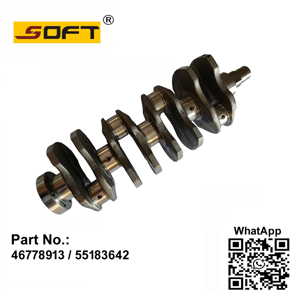
Catastrophic bottom-end failure in commercial and fleet vehicle rebuilds carries massive operational impacts. Navigating the technical variances between OEM specifications and aftermarket options when sourcing a Fiat Crankshaft poses a significant challenge for engine builders. Minute deviations in journal tolerances quickly lead to premature bearing wear, spun bearings, or complete engine failure. Fleet managers and machine shops need a stringent technical framework for evaluating, validating, and procuring these components. This guide provides a comprehensive methodology for large-scale replacement engine programs. You will learn how to assess metallurgy, ensure dimensional accuracy, verify electronic integration, and validate supplier reliability. By adhering to strict engineering standards, you mitigate risks and ensure long-term engine durability. Proper validation prevents catastrophic failures on the road and keeps fleet vehicles operational under heavy duty cycles.
Dimensional Accuracy is Non-Negotiable: Main and rod journal tolerances must align strictly with Fiat’s original engineering specifications to maintain proper oil clearances and hydrodynamic lubrication.
Tone Wheel and Sensor Phasing: Modern Fiat engine crankshafts require exact reluctor ring alignment for precise crankshaft position sensor data; misalignment causes immediate timing faults.
Metallurgical Integrity Dictates Lifespan: The choice between nodular cast iron and forged steel must align with the specific engine load requirements and duty cycles of the replacement program.
Surface Treatment Verification: Proper induction hardening or nitriding is critical; unverified surface treatments lead to rapid journal degradation.
Supplier Validation Mitigates Risk: Procuring a replacement crankshaft for Fiat engines requires rigorous vetting of the manufacturer’s quality control processes, including ISO certifications, non-destructive testing (NDT) protocols, and secure transit packaging.
Success Criteria for Fiat Engine Crankshaft Replacement
Defining Baseline Fitment Tolerances
Cross-reference specific engine families before procurement. Platforms like the FIRE 1.2L/1.4L, Multijet diesel 1.3L/1.6L, and TwinAir possess entirely different block architectures. Exact stroke and journal matches remain mandatory. You must establish acceptable variances for main journal and crankpin diameters. These measurements typically fall within ten-thousandths of an inch. Even minor deviations disrupt the hydrodynamic oil wedge. This disruption causes immediate metal-to-metal contact, wiping the soft lead-indium overlay right off the bearing shells.
Thrust bearing surface finish dictates axial end-play specifications. Excessive end-play damages the engine block and transmission input shaft. Insufficient end-play causes rapid thrust bearing failure due to overheating and oil starvation. Stroke length accuracy heavily impacts static compression ratios. It also determines critical piston-to-valve clearances. A stroke variance of just a fraction of a millimeter alters engine timing. This leads to poor combustion efficiency or catastrophic valve collision at high RPMs.
Machine shops must implement strict measurement protocols upon receiving new parts. Wipe the journals with a lint-free solvent rag to remove shipping oils. Zero your outside micrometer using a calibration standard. Measure the journal at the 12 o'clock and 3 o'clock positions. Move the micrometer to the edges of the journal to check for taper. Record all measurements on a build sheet and compare these figures directly to the factory service manual.
Measure all main journals using a calibrated outside micrometer.
Verify crankpin diameters across multiple axes to check for out-of-roundness.
Confirm the thrust bearing width matches the engine block saddle dimensions.
Calculate the exact stroke length using a dial indicator setup on a V-block stand.
Inspect the snout diameter to ensure a tight interference fit with the timing gear.
Rotational Dynamics and Balancing Requirements
Evaluate static and dynamic balancing standards rigorously. Modern engines operate at high RPMs, requiring precise rotational dynamics. You must match bob-weight specifications to the specific Fiat engine crankshaft application. Reciprocating mass and rotating mass calculations dictate the required counterweight mass. Incorrect bob-weight calculations lead to severe harmonic vibrations. These vibrations destroy main bearings rapidly, loosen flywheel bolts, and crack engine blocks.
Harmonic dampener fitment requires precise keyway integrity. The keyway must securely lock the dampener to the snout. Any slop in this connection destroys the timing gear and shears the woodruff key. Evaluate the balancing grade according to ISO 1940-1 standards. Most automotive applications require a G6.3 balancing grade or better. High-performance or heavy-duty diesel variants often demand stricter G2.5 tolerances. Always perform a final dynamic balance check with the specific flywheel and harmonic balancer attached to the rotating assembly.
Drill holes in the counterweights indicate factory balancing efforts. Inspect these holes for sharp edges. Sharp edges create stress risers that can initiate cracks under torsional load. A quality manufacturer will chamfer or radius the edges of all balancing holes. If you are building a fleet of identical engines, standardize your piston and connecting rod weights. This allows you to order pre-balanced rotating assemblies, saving hours of machine shop labor per unit.
Reluctor Ring and Tone Wheel Integration
Evaluate press-fit versus integrated tone wheels carefully. The crankshaft position sensor relies entirely on this component to dictate ignition timing and fuel injection events. Validate tooth count, gap placement, and phasing angles. Specific ECU requirements demand exact alignment. A misaligned tone wheel causes immediate no-start conditions. It also triggers persistent engine misfire codes and cam/crank correlation faults.
Ensure the reluctor ring material resists demagnetization. It must also withstand high thermal distortion inside the crankcase. Press-fit rings can slip if the interference fit is incorrect. Integrated tone wheels eliminate slipping risks but complicate the machining process. Verify the runout of the tone wheel teeth using a dial indicator. Excessive runout causes erratic sensor readings, timing drift, and random engine stalling.
The 60-2 tone wheel configuration is common in many modern platforms. If the aftermarket manufacturer presses this wheel on with a 2-degree phase shift, the engine suffers from permanent timing retard or advance. The ECU cannot compensate for physical misalignment. Build a simple jig using a degree wheel and a pointer to verify the missing tooth aligns exactly with the factory specification at Top Dead Center (TDC).
Material and Manufacturing Approaches for Replacement Programs
Forged Steel vs. Nodular Cast Iron
Assess tensile strength and fatigue resistance carefully during procurement. Forged steel suits high-compression or turbocharged diesel applications perfectly. The forging process aligns the grain structure of the metal. This alignment provides superior resistance to bending and torsional stress. Evaluate nodular cast iron for standard-duty programs. Naturally aspirated engines often utilize ductile iron effectively without compromising longevity.
Nodular iron contains graphite nodules that provide excellent dampening properties against harmonic vibrations. It costs less to manufacture than forged steel. However, it lacks the ultimate tensile strength required for heavy-duty cycles or forced induction. Analyze the performance ratios of billet machining versus traditional forging. Billet components offer extreme strength but carry high manufacturing costs. Select the material based strictly on the intended duty cycle of the fleet vehicle.
When inspecting a forged unit, look for the wide parting line on the counterweights. This indicates a true forging process. Cast units typically feature a narrow, sharp parting line. Do not install a cast iron unit in a commercial diesel application. The high cylinder pressures will eventually snap the component right at the rod journal fillet.
Material Type
Tensile Strength
Manufacturing Indicator
Best Application
Fatigue Resistance
Nodular Cast Iron
600-800 MPa
Narrow, sharp parting line
Naturally Aspirated, Standard Duty
Good
Forged Steel (4340)
1000+ MPa
Wide, flat parting line
Turbocharged, Heavy Duty Diesel
Excellent
Billet Steel
1200+ MPa
CNC tool marks, no parting line
High-Performance, Extreme Duty
Superior
Surface Hardening and Finishing Techniques
Induction hardening provides a specific depth of hardness. This process uses electromagnetic induction to heat the journal surfaces. The metal is then rapidly quenched to increase surface hardness. This depth affects future regrinding capabilities during subsequent rebuilds. Shallow hardening depths limit the component to a single lifecycle. Once you grind past the hardened layer, the soft core metal will destroy the bearings in minutes.
Gas nitriding diffuses nitrogen into the surface of the steel. It extends fatigue life significantly during heavy-duty cycles. It also prevents microscopic surface cracks from propagating. Micro-polishing journal surfaces is an absolute requirement. Smooth surfaces ensure optimal bearing longevity. Rough journals will shred soft bearing materials instantly. Target a Roughness Average (Ra) of less than 10 micro-inches.
Check the fillet radii during your surface inspection. The transition from the journal surface to the counterweight web must be smooth. Performance applications use rolled fillets to compress the grain structure and prevent stress risers. If the grinding wheel leaves a sharp corner at the fillet, the metal will snap at that exact location under heavy load. Use a radius gauge to confirm the fillet matches the bearing shell chamfer.
Verify the hardening method used by the manufacturer via material data sheets.
Request documentation detailing the exact case hardness depth.
Perform Rockwell hardness tests on sample units upon delivery.
Inspect journal surfaces for proper micro-polishing cross-hatch patterns.
Use a profilometer to verify the Roughness Average (Ra) is below 10 micro-inches.
Check all fillet radii with a radius gauge to ensure clearance with the bearing chamfer.
Evaluating a Replacement Crankshaft for Fiat Engines
OEM vs. Aftermarket Fitment Realities
Analyze the gap between genuine parts and aftermarket alternatives. Evaluate aftermarket engineering drawings against OEM blueprints meticulously. Reverse engineering complex engine components introduces dimensional risks. Assess the severe risks associated with universal fit components. Engine-specific rebuilds require exact dimensional matching. A replacement crankshaft for Fiat must meet stringent factory parameters to survive commercial use.
Coordinate Measuring Machine (CMM) data provides objective dimensional proof. Demand this data from aftermarket suppliers before placing volume orders. Compare the fillet radii of the aftermarket unit to the original. Incorrect fillet radii cause stress concentrations and premature snapping. Ensure the snout diameter matches the factory timing gear perfectly. Loose timing gears destroy engines upon initial startup.
Look closely at the oil gallery intersections. OEM units feature smooth, deburred intersections inside the cross-drilled holes. Cheap aftermarket units often leave hanging burrs inside the oil passages. These burrs break off during engine operation, travel directly into the rod bearings, and cause immediate catastrophic failure. Always run a rifle brush through every oil passage to check for internal machining debris.
Bearing Clearance and Oil Flow Validation
Navigate the factory color-coded bearing grading system carefully. This ensures you accurately match the component to the engine block. Verify oil hole chamfering and cross-drilling alignment. Proper lubrication depends on unobstructed oil flow through the galleries. Sharp edges on oil holes scrape bearing material away. Proper chamfering promotes a consistent hydrodynamic oil wedge.
Calculate required bearing crush based on supplied dimensions. Measure clearances using precise dial bore gauges. Do not rely solely on plastigage. Install the main bearings into the block and torque the main caps to factory spec. Use a dial bore gauge zeroed to your micrometer reading of the main journal. Measure the vertical clearance. This gives you the exact oil clearance.
Target clearances typically range from 0.0015 to 0.0025 inches. High-performance diesel engines may require slightly looser clearances to accommodate thicker oil viscosity and higher thermal expansion. Anything tighter risks wiping a bearing on cold starts. Anything looser drops oil pressure at idle. Always prime the oil system with a pressurized tank before rotating the assembly for the first time.
Compliance, Testing, and Quality Assurance
Mandatory non-destructive testing detects hidden manufacturing flaws. Magnetic particle inspection (Magnaflux) reveals surface cracks effectively. Ultrasonic testing uncovers internal material defects like porosity and inclusions. Evaluate supplier ISO 9001 and IATF 16949 certifications. These certifications prove the manufacturer follows strict automotive quality standards. Uncertified suppliers introduce unacceptable risks into fleet rebuild programs.
Request comprehensive metallurgical test reports for every batch. Interpret coordinate measuring machine data to confirm dimensional accuracy. Check for core shift in cast iron units. Core shift causes uneven wall thickness and severe rotational imbalance. Reject any batch that lacks proper material certification sheets. Quality assurance must occur before the components leave the manufacturing facility.
Perform your own spot checks upon receiving a pallet of parts. Select one unit at random and send it to an independent metallurgy lab. Have them verify the alloy composition and the depth of the induction hardening. This independent verification keeps suppliers honest and prevents a bad batch of parts from destroying an entire fleet of rebuilt engines.
Overall Value and Procurement Trade-Offs
Logistics, Packaging, and Core Management
Evaluate outright purchase models versus core exchange programs. Fleet operators must optimize inventory management and warehouse space. Anti-corrosion packaging remains essential for long-term warehouse storage. Utilize Volatile Corrosion Inhibitor (VCI) bags to prevent rust. Cosmoline coatings offer excellent protection but require extensive pre-installation cleaning with mineral spirits or hot tanks. Select the packaging method based on your storage timeline and shop cleaning capabilities.
Custom crating prevents transit damage effectively. Precision-machined journals and tone wheels require robust physical protection. Dropped crates bend the component or shatter the reluctor ring. Ensure the supplier uses suspension blocks inside the crate. These blocks isolate the heavy metal from impact shocks. Inspect all crates for external damage immediately upon delivery.
Establish a strict protocol for receiving shipments. Do not let parts sit in a damp warehouse without inspecting the VCI bags. A small tear in the plastic allows moisture to enter, flash-rusting the polished journals in a matter of days. If you find torn packaging, clean the unit immediately, coat it in assembly lube, and repackage it securely.
Warranty and Supplier Liability
Analyze the exact scope of supplier warranties carefully. Determine if coverage includes parts replacement or labor costs. Engine extraction and teardown labor often exceed the part cost. Establish clear service level agreements for defect rates. Define return merchandise authorization protocols upfront. Hold suppliers accountable for dimensional inaccuracies discovered during assembly.
Require root cause analysis (RCA) reports for any failed units. This prevents recurring defects in future shipments. Negotiate warranty terms that protect your operational budget. Ensure the supplier carries adequate product liability insurance. Document all pre-installation measurements to support potential warranty claims. Clear documentation eliminates disputes over installation errors versus manufacturing defects.
If a unit fails in the field, do not return it immediately. Disassemble the engine in-house and document the failure mode with photographs. Measure the remaining journals. Check the oil filter for bearing material. Build a comprehensive failure report before contacting the supplier. This data forces the supplier to address the manufacturing flaw rather than blaming the engine builder.
Implementation Risks and Mitigation Strategies
Identifying Substandard and Counterfeit Components
Watch for red flags during visual inspections. Poor casting flash removal indicates low manufacturing quality. Inconsistent journal finishes lead to immediate bearing failure. Misaligned oil galleries starve the engine of critical lubrication. Avoid undocumented offshore manufacturing sources entirely. Counterfeit parts cause catastrophic engine failures and safety hazards.
Check the weight of the unit against OEM specifications. Counterfeiters often use inferior, lighter alloys to cut costs. Inspect the stamped or laser-etched part numbers. Counterfeit fonts often look slightly distorted or misaligned. Verify the supplier's authorized distribution status. Direct factory sourcing minimizes the risk of receiving counterfeit components.
Look at the oil gallery plugs. High-quality units use threaded pipe plugs secured with high-strength threadlocker. Substandard units often use cheap press-in cup plugs. These cup plugs can blow out under high oil pressure, instantly dumping all engine oil back into the pan and seizing the engine.
Inspect oil gallery plugs for proper sealing and deep thread engagement.
Check for excessive porosity or pitting on non-machined surfaces.
Verify the presence of factory-correct balancing drill holes.
Ensure the keyway is machined perfectly parallel to the snout centerline.
Weigh the component and compare it to a known good OEM unit.
Pre-Installation Inspection Protocols
Implement mandatory in-house micrometer checks prior to assembly. Use dial bore gauges to verify bearing clearances accurately. Verify straightness on V-blocks to detect shipping damage. Place the end journals on V-blocks and measure the center journal runout with a dial indicator. Runout should not exceed 0.001 to 0.002 inches. Excessive runout binds the engine and destroys main bearings.
Inspect reluctor ring runout and tooth integrity. This prevents electronic timing failures upon startup. Clean all oil passages thoroughly using rifle brushes. Remove machining debris and cosmoline before installing the component. Use high-pressure solvent tanks to flush internal cross-drilled holes. Blow out all galleries with compressed air. Cleanliness dictates the lifespan of the rebuilt engine.
Never assume a new part is ready to install out of the box. Treat every new component as a raw casting that requires final verification. Mount the unit on an engine stand and thread a chaser tap into the flywheel flange holes. Factory threads often contain burrs or leftover cutting fluid that will cause flywheel bolts to yield prematurely during final torque sequences.
Conclusion
Initiate a pilot order of 5 to 10 units for thorough physical, dimensional, and metallurgical inspection before committing to volume procurement.
Request comprehensive metallurgical documentation, CMM data, and NDT reports directly from the manufacturer for every batch received.
Consult your machining department to verify bearing availability and exact oil clearance requirements for the specified journal dimensions.
Establish a strict in-house pre-installation cleaning protocol to remove all anti-corrosion coatings and internal machining debris.
FAQ
Q: Does the specific Fiat engine family affect crankshaft selection?
A: Yes. Platforms like FIRE, Multijet, and TwinAir possess entirely different stroke, journal, and balancing requirements. Exact engine code verification remains the mandatory first step in procurement to avoid catastrophic fitment errors.
Q: What are the standard main journal tolerances for a Fiat engine crankshaft?
A: Tolerances typically range within ten-thousandths of an inch. You must reference specific engine codes and perform precise micrometer verification to ensure proper hydrodynamic lubrication and bearing crush.
Q: How do I ensure the tone wheel on my replacement crankshaft for Fiat is correctly phased?
A: Compare the reluctor ring alignment against the original OEM component. Use a degree wheel or specialized alignment jig to verify phasing angles and prevent severe ECU timing errors.
Q: How do I verify the surface hardness of a replacement crankshaft for Fiat?
A: Utilize Rockwell hardness testing equipment on sample units. Always request material certification sheets from the manufacturer to confirm induction hardening or nitriding depths meet factory specifications.
Q: Can a cast iron Fiat crankshaft be used in a turbocharged application?
A: Cast iron has severe limitations under high cylinder pressures. Forged steel is highly recommended for forced induction or heavy-duty diesel variants to prevent fatigue failure and snapping.
Q: What is the acceptable runout for a new Fiat crankshaft?
A: Runout should typically not exceed 0.001 to 0.002 inches when measured on the center main journal with the ends supported on V-blocks, depending on the specific engine manual.
Q: Why is oil hole chamfering critical on a replacement crankshaft?
A: Proper chamfering prevents stress risers and reduces cracking risks. It also promotes a consistent hydrodynamic oil wedge, protecting the soft bearing materials from premature wear and scoring.
Ningbo Dingjia Auto Parts Co., Ltd. is a professional enterprise specialized in manufacturing engine camshafts, connecting rods, crankshafts, and carbon fiber modification parts.